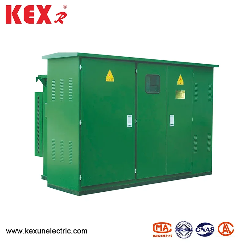
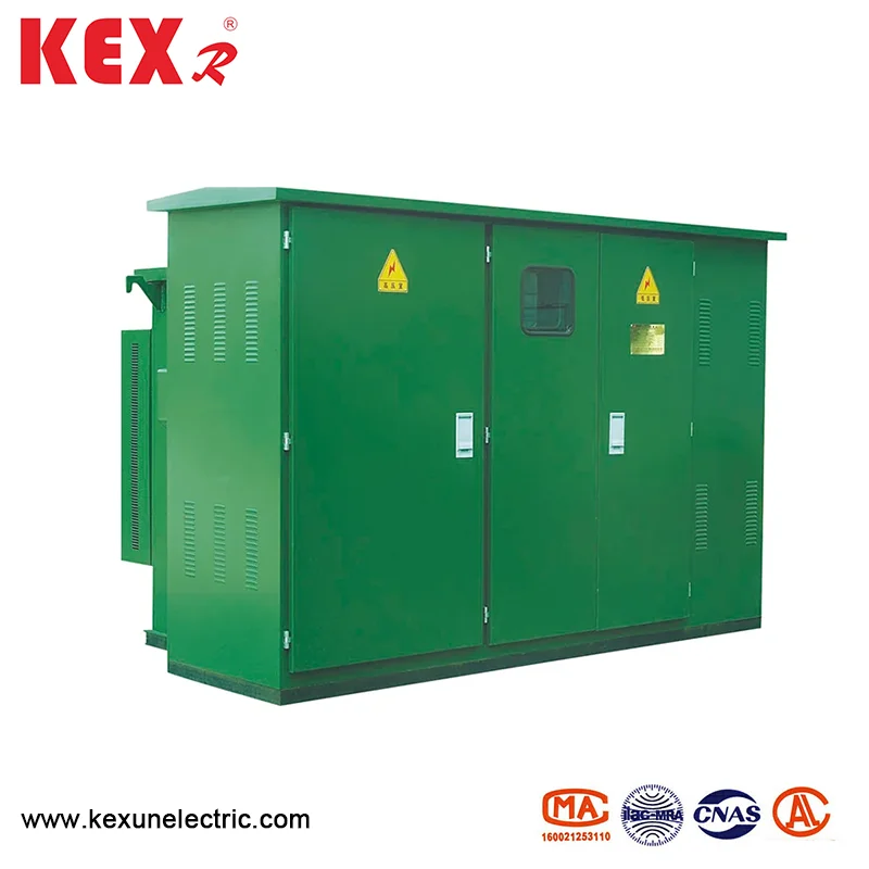
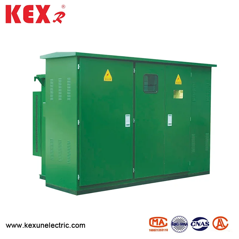
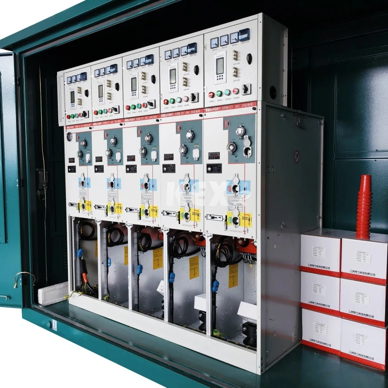
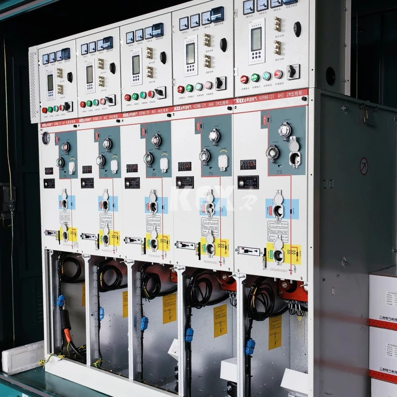
Combined Type GIS Cabinet
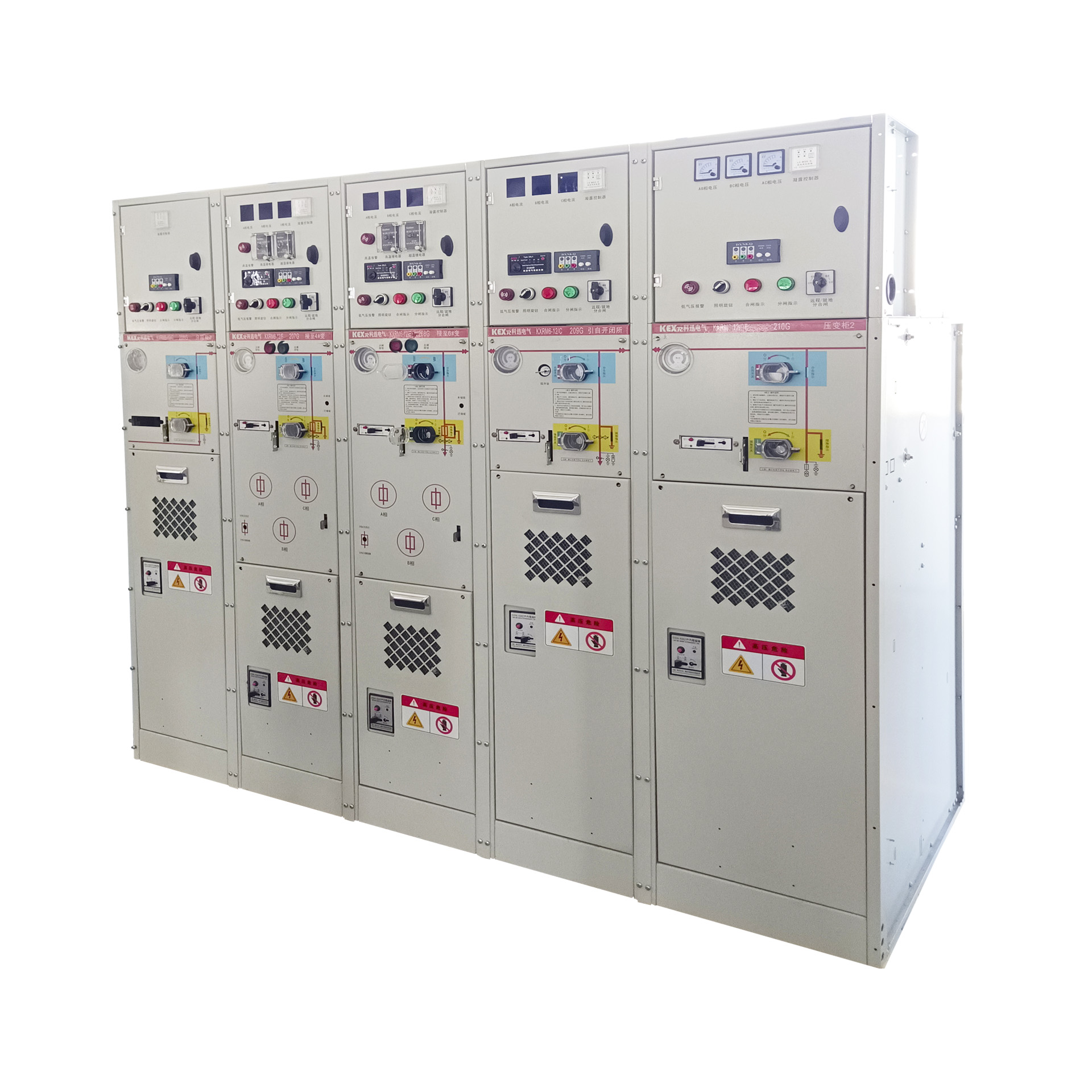
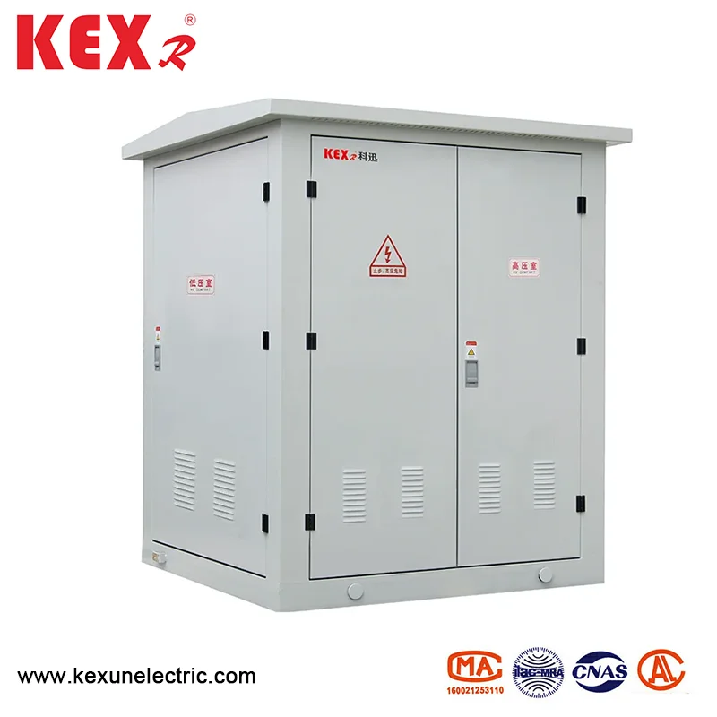
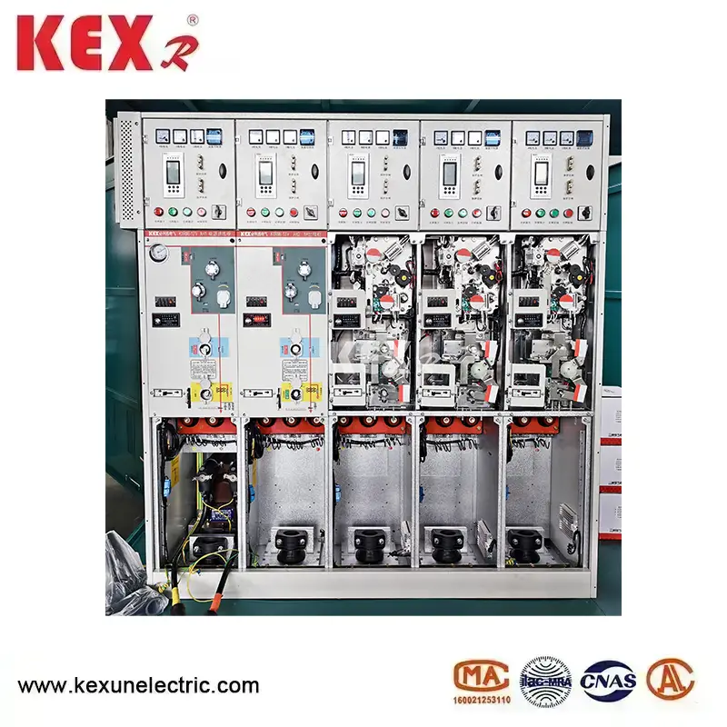
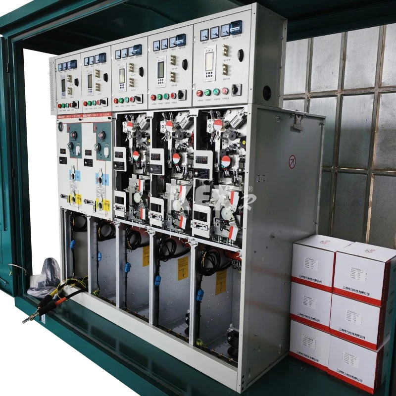
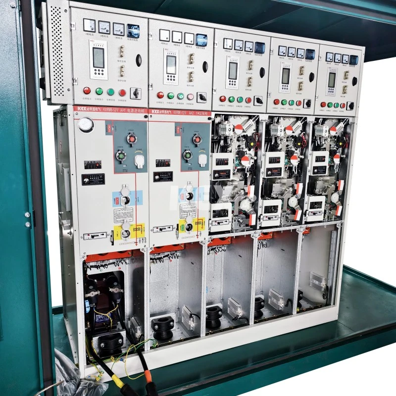
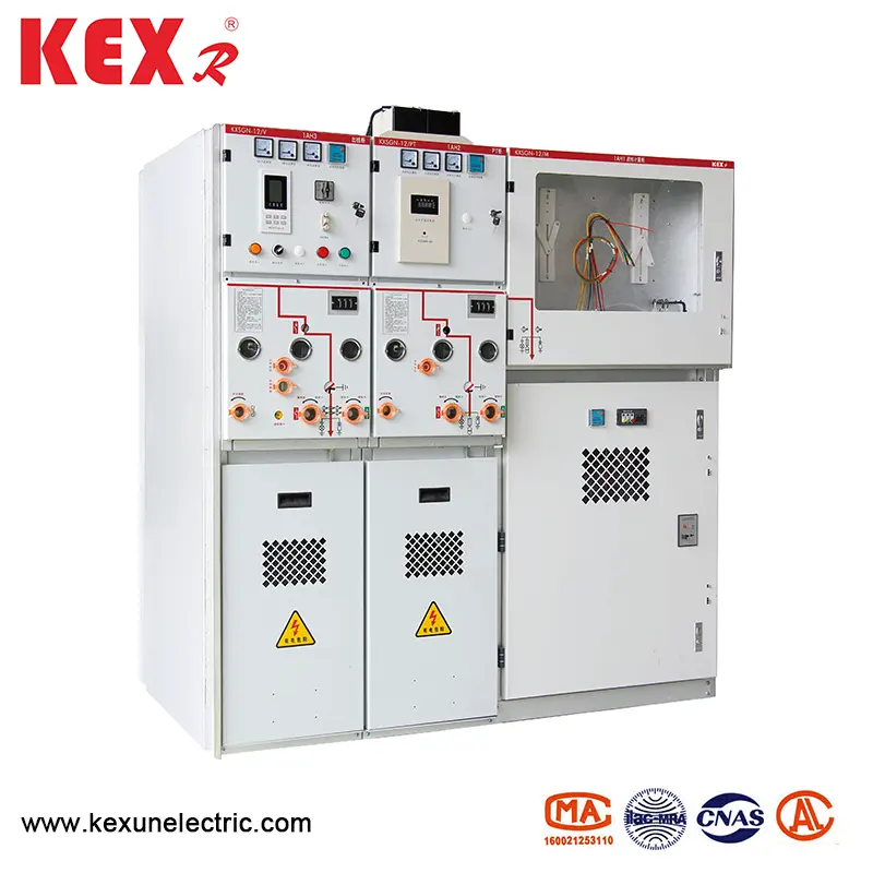
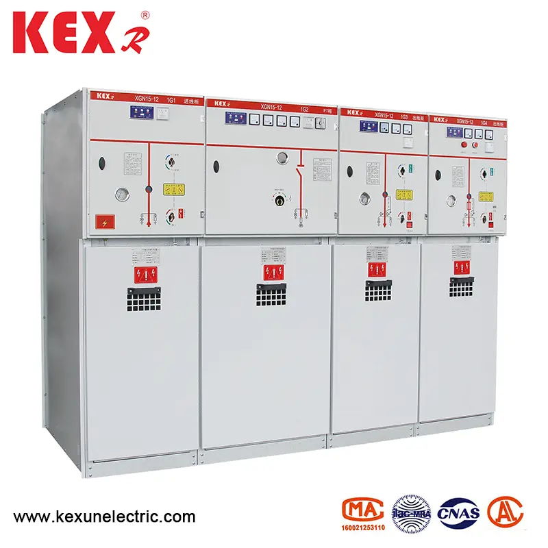
KXRM6-12 Combined Type GIS Cabinet independently developed and produced by Kexun Electric is widely used in 10kV/6K distribution system. Switch cabinet is modular unit mode, which can be combined according to different purposes; There are two categories: fixed unit combination and expandable unit, which meet the needs of flexible use of compact switchgear in various substations and are the first choice switch products for various urban and rural users' power distribution systems.
Model: KXRM6-12
Brand:KEXR
Model: KXRM6-12
Brand:KEXR
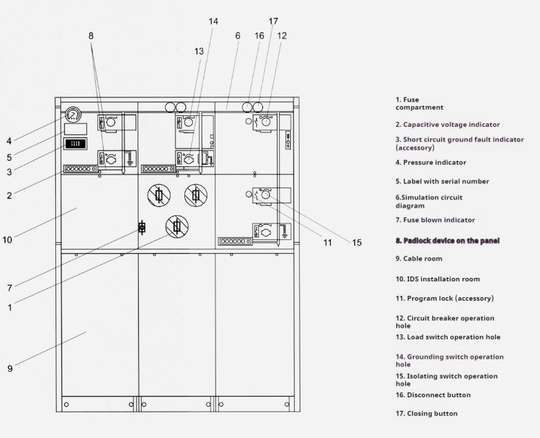
●Components
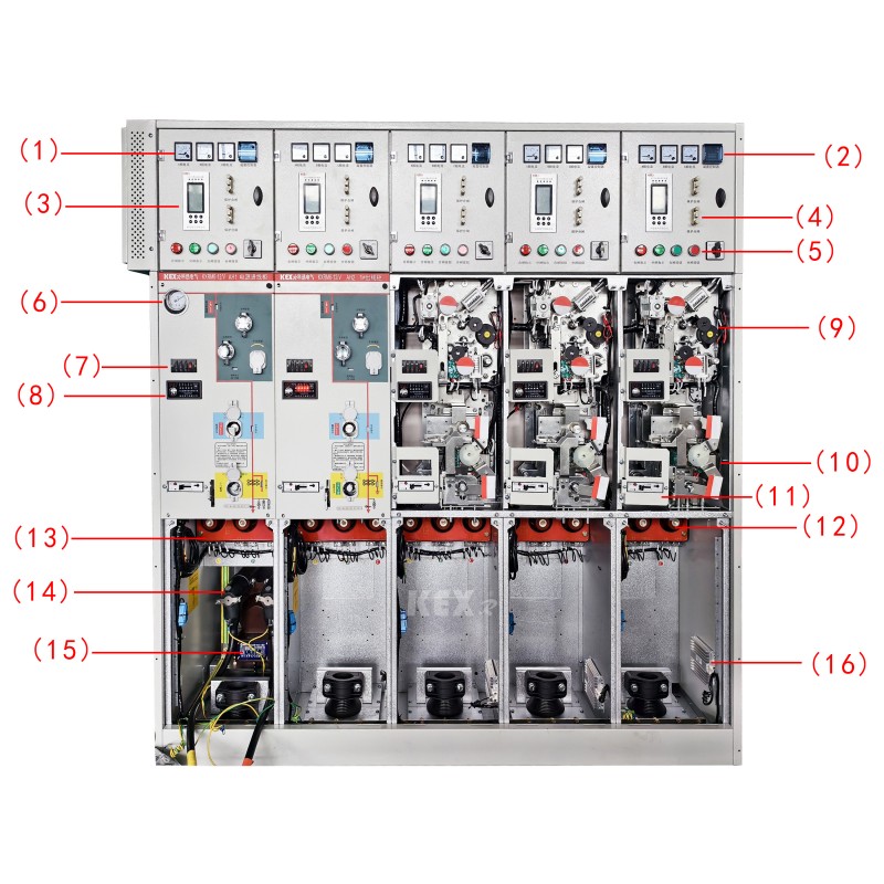
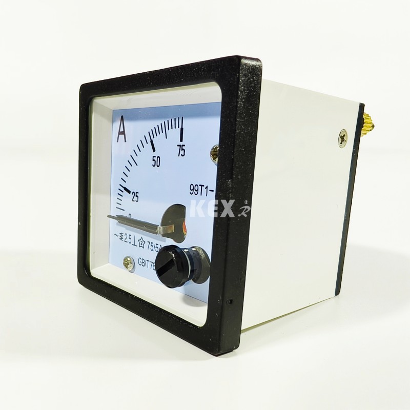
1.Ammeter
 2.Condensation controller
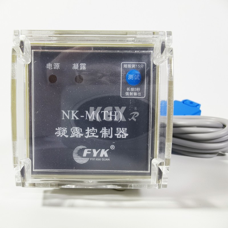
3.Microcomputer protection device

6 .Barometer
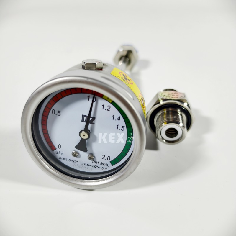
7.Charged display
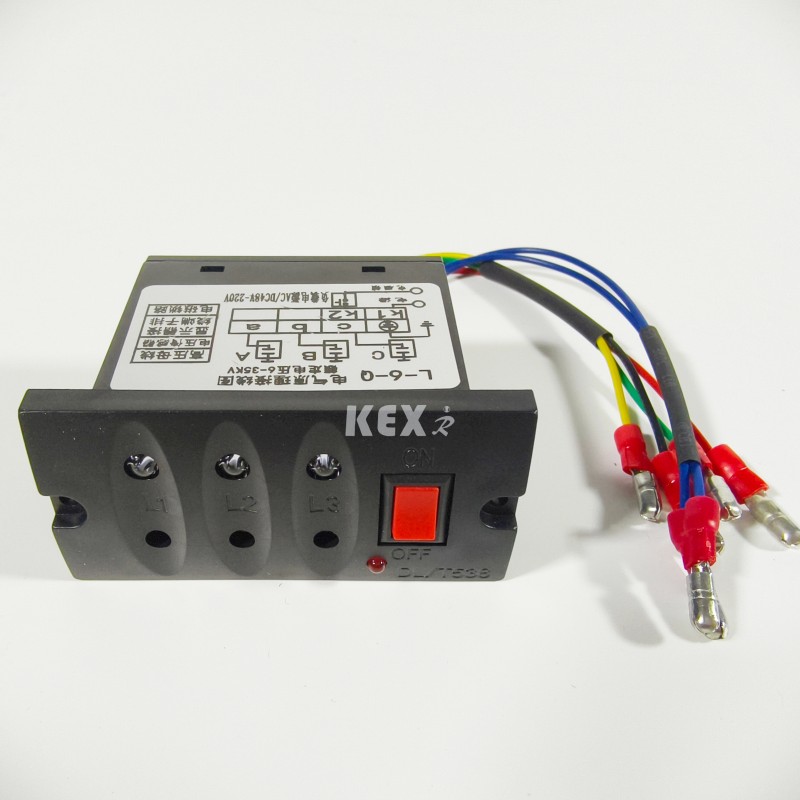
8.. Fault indicator
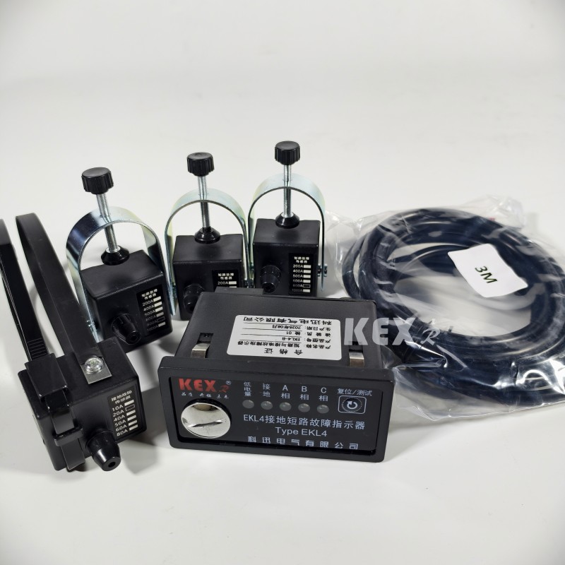
9. Electric operating mechanism
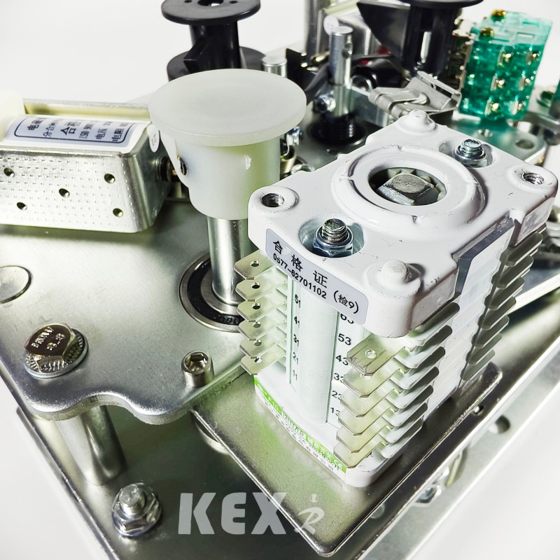
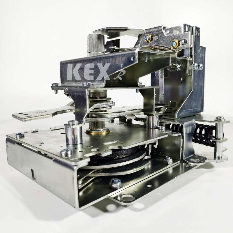
10. Manual operating mechanism
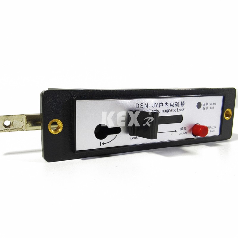
11. Electromagnetic lock
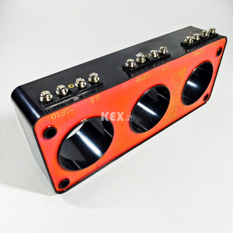
12~13 . Current transformer
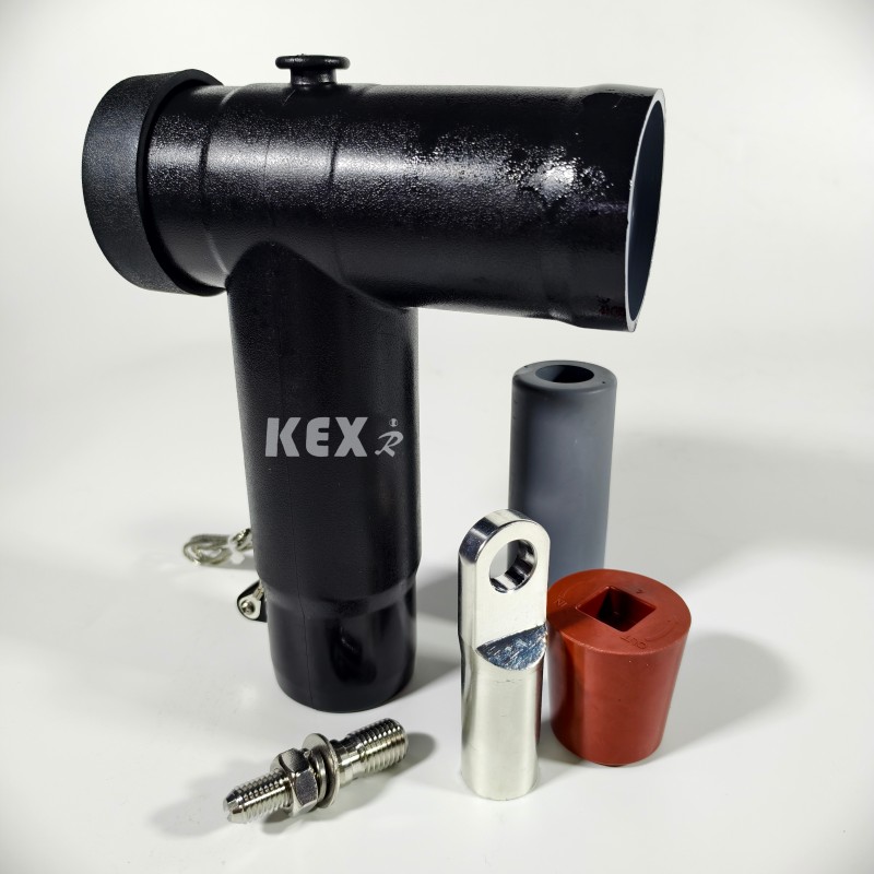
14.Cable plug
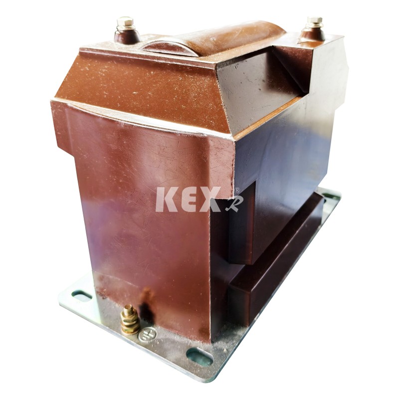
15.Voltage transformer
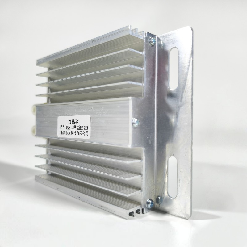
16 .Aluminum alloy heating plate
● Using conditions
KXRM6-12 Combined Type GIS Cabinet is suitable for high and low temperature (+40℃~-40℃), humidity, dust, salt pollution, mines, high altitude (1000m) and other environments. Short-term immersion in water within 24 hours does not affect the use. Note: If the altitude is higher, please indicate the specific altitude.
● Standards
KXRM6-12 Combined Type GIS Cabinet meets the standards below
IEC60056、IEC60298、IEC60129、IEC60420、IEC60265、IEC60694 etc...
GB3804、GB3906、GB11022 etc...
● Main advantages
◆ SF6 gas in KXRM 6-12 Combined Type GIS Cabinet is used as arc extinguishing and insulating medium.
◆ The switch cabinet is fully sealed and insulated; Busbars, switches and live parts are completely enclosed in stainless steel shell.
◆ The cavity is filled with 1.4bar SF6 gas, and the protection level reaches IP67: the whole switch device is completely unaffected by external environmental conditions, which can ensure the normal operation of the switch even in extreme cases such as short-term water immersion, and the product is maintenance-free.
◆ The switch cabinet has a perfect "five-prevention" interlocking device, which completely eliminates the operation failure of personnel and equipment that may be caused by human misoperation.
◆ All switch cabinets have reliable safe pressure relief channels, which can ensure the personal safety of operators even in extreme cases.
◆ Cabinet is divided into fixed unit combination and expandable unit combination.
◆ Cabinet usually enters and exits from the front, and it can also be extended or extended from the side according to different installation positions.
◆ The size of the cabinet is convenient to install, and it can be suitable for places with narrow space and poor environmental conditions.
◆ Cabinet can be equipped with electric, remote control and monitoring devices according to different needs of users.
● Mainly Technical parameters table
|
Item |
Unit |
C Module |
F Module |
V Module |
CB Module |
||
|
|
Load switch |
Combined |
Vacuum switch |
Isolate Switch/Ground switch |
VCB |
Isolate Switch/Ground switch |
|
|
Rated voltage |
KV |
12/24 |
12/24 |
12/24 |
12/24 |
12/24 |
12/24 |
|
Working frequency withstand voltage |
KV |
42/50 |
42/50 |
42/50 |
42/50 |
42/50 |
42/50 |
|
Lightning impulse withstand voltage |
KV |
95/125 |
95/125 |
95/125 |
95/125 |
95/125 |
95/125 |
|
Rated current |
A |
630/630 |
NOTE1 |
630/630 |
|
1250/630 |
|
|
Breaking current |
A |
630/630 |
|
|
|
|
|
|
Cable breaking current |
A |
135/135 |
|
|
|
|
|
|
5% Load breaking current |
A |
31.5/- |
|
|
|
|
|
|
Grounding fault breaking current |
A |
200/100 |
|
|
|
|
|
|
Grounding fault cable charging breaking current |
A |
115/87 |
|
|
|
|
|
|
Short-circuit breaking current |
KA |
|
NOTE2 |
20/16 |
|
25/20 |
|
|
Closing ability |
KA |
63/52.5 |
NOTE2 |
50/40 |
50/40 |
63/50 |
63/50 |
|
Short-term withstand current (2s) |
KA |
25/- |
|
|
|
|
|
|
Short-term withstand current (3s) |
KA |
-/21 |
|
20/16 |
20/16 |
25/20 |
25/20 |
|
Mechanical life |
Time |
5000 |
3000 |
5000 |
2000 |
5000 |
5000 |
NOTE1:Depends on the rated current of fuse
NOTE2:Depends on the high voltage fuse
● Each module of Combined Type GIS Cabinet has the following configuration
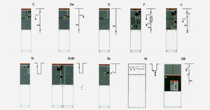
▶D cabinet configuration See "Cable Connection Module without Grounding Knife" for standard configuration and characteristics.
▶Configuration of C cabinet See "Load Switch Module" for standard configuration and characteristics.
▶F cabinet configuration See "Vacuum Switch Module" for standard configuration and characteristics.
The KX-RM6 Combined Type GIS Cabinet standard combination can also provide the following configurations
▶Capacitive voltage indicator of incoming bushing
▶Each air chamber is equipped with a pressure gauge for monitoring SF6 density.
▶Lifting lug
▶Operating handle
Example:
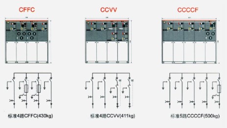
□ Load switch Module C
○ Standard configuration and features
▶630a busbar
▶Three-station load/grounding switch
▶Three-station single spring operating mechanism with two independent load switches and grounding switch operating shafts.
▶Position indication of load switch and grounding switch
▶Horizontal outgoing bushing at the front, 630A 400 series bolt bushing.
▶Capacitive voltage indicator for indicating bushing electrification
▶For all the switch functions, it is convenient to install a padlock device on the panel.
▶SF6 gas pressure gauge (only one in each SF6 gas box)
▶Grounding busbar
▶Interlocking between grounding switch and front panel of cable room
○ Optional configurations and features
▶Reserved bus extension
▶External bus
▶Load switch electric operating mechanism DC24V/48V/110V/220V; AC 110V/220V;
▶Short circuit and ground fault indicator Measuring ring current transformer and ammeter
▶Measuring ring current transformer and watt-hour meter
▶Lightning arrester or double cable head can be installed at the cable inlet sleeve.
▶Key interlock Incoming line live grounding locking (locking grounding switch when bushing is live) AC/DC 110 V/220 V. auxiliary contact
▶Load switch position 2NO+2NC, grounding switch position 2NO+2NC, pressure gauge 1NO with signal, and arc extinguisher 1NO with signal contact.
▶The secondary device can be installed in
▶Secondary line chamber at the top of switch cabinet, low voltage box at the top of switch cabinet.
□ Load switch and fuse combined Module F
○ Standard configuration and features
▶630a busbar
▶Three-station load switch, the first end of fuse is mechanically linked with the grounding switch at the end of fuse.
▶Three-station spring operating mechanism, with two independent load switches and grounding switch operating shafts.
▶Position indication of load switch and grounding switch
▶Fuse barrel
▶The fuse is placed horizontally.
▶Fuse trip indication Horizontal outgoing bushing at the front, 200 series plug-in bushing of 200A.
▶Capacitive voltage indicator for indicating bushing electrification
▶For all the switch functions, it is convenient to install a padlock device on the panel.
▶SF6 gas pressure gauge (only one in each SF6 gas box)
▶Grounding busbar
▶The fuse parameters for transformer protection are 12KV, max 125A, 24KV and max 63A.
▶Interlocking between grounding switch and front panel of cable room.
○ Optional configurations and features
▶Reserved busbar extension
▶External bus Motor for load switch operation 24V/48V DC 110V/220V DC/AC.
▶Parallel trip coil 24V/48V DC 110V/220V DC/AC.
▶Parallel closing coil 24V/48V DC 110V/220V DC/AC.
▶Measuring ring current transformer and ammeter Measuring ring current transformer and watt-hour meter
▶Incoming line live grounding locking (locking grounding switch when bushing is live) AC/DC 110 V/220 V. auxiliary contact
▶Load closing position 2NO+2NC, grounding switch position 2NO+2NC, fuse blowing 1NO, pressure gauge 1NO with signal, and arc extinguisher 1NO with signal contact.
▶The secondary device can be installed in the secondary line chamber at the top of the switch cabinet and the low voltage box at the top of the switch cabinet.
□ Meter Module M
○ Standard configuration and features
▶12KV metering cabinet
▶2 current transformers
▶2 voltage transformers
▶6pcs 400-series bushings are used to connect the flexible extended external bus of GSFR6-12, with the upper inlet and the lower outlet.
▶Flame breaker for protecting PT
▶Low pressure component 1 voltmeter with changeover switch, 1 ammeter with changeover switch, width x height x depth =696×1806×820mm.
○ Optional configurations and features
▶3 current transformers
▶3 voltage transformers lightning arrester
▶Capacitive voltage indicator for indicating that switchgear is charged
▶Low pressure component :1 power meter, 1 reactive power meter.
□ VCB Module CB
○Standard&Optional configuration and features
▶Lightning arrester is installed at the incoming cable of 1250a/630a busbar.
▶Vacuum circuit breaker for line protection of 1250a/630a
▶Current transformer
▶Vacuum circuit breaker VD4X0 electrically operated 10VDC
▶Voltage transformer
▶Electric operation of UXO, an upper three-station isolating/grounding switch of vacuum circuit breaker. ▶Protection and control unit REF542plus (with protective CT)
▶Shunt trip coil 110V/220V DC
▶Closing coil 110V/220VDC
▶400-series bolt bushing of outlet bushing 1250A/630A arranged horizontally at the front.
▶Reserved Bus Extension of Capacitive Voltage Indicator 1250A/630A for Indicating Bushing Live
▶SF6 gas pressure gauge (only one in each SF6 gas box) Width x height x depth = 696× 1806× 781 mm. ▶On-off sequence: O-0.3s-CO-180s-CO.
▶Gas pressure sensor
□ Optional accessories
1. Auxiliary contact All load switches and circuit breakers can be equipped with 2NO+2NC indicating switch position. A parallel trip coil (AC or DC) can be installed on the transformer switch and circuit breaker, and the low-voltage control component is located behind the front panel.
2. Voltage indication Capacitive voltage indicator shows whether the bushing is charged or not, and the socket on it can be used for nuclear phase.
3. Short circuit and ground fault indicator In order to facilitate fault location, the cable switch module can be equipped with short circuit and grounding fault indicators for simple fault detection.
4. Electric operation It is a standard scheme for manual operation mechanism of cable switch unit and transformer unit. You can also choose to install an electric operating mechanism. Cable switches, vacuum circuit breakers and grounding switches are all operated by mechanisms located behind the front panel. All switches and circuit breakers can be operated by operating handle (standard configuration), or can be equipped with motor operating mechanism (accessories). However, the grounding switch can only be operated manually, and a mechanism with the ability to close the fault current is configured. The electric operating mechanism can be easily realized by stages.
5. Cable connection Standard bushings in accordance with DIN47636 are installed. All bushings have the same height from the ground and are protected by cable room cover plate. Some cover plates can be interlocked with the grounding switch, and special double cable room cover plates can also be used for double cable incoming lines.
6. Pressure indicator Usually equipped with a pressure indicator, which is formed by a pressure gauge. In addition, electrical contacts can be provided to indicate the pressure reduction.
7. Key lock Key locks for circuit breakers, load switches and grounding switches can be installed. It can be equipped with lock interlocking semi-shelter, which is suitable for circuit breakers, load switches and grounding switches.
8. Arc interrupter All ring network units can be equipped with arc arresters. When arcing occurs inside, the arc arresters will automatically close on the incoming bushing, including D, DE and V modules, and all cable modules can be equipped with an arc arrestor. They must order with the unit and can't change it. The action of arc extinguisher can be indicated by this method, and the electrical contacts in SF6 cabinet are connected to the terminal behind the front panel.
● Scheme example
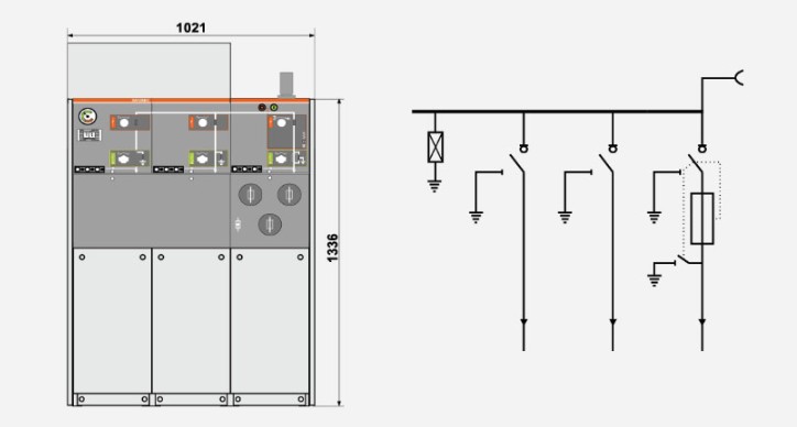
◆ Scheme 1 SA+CCF+
Install lightning arrester on the bus and leave it for expansion.
Note: The number of switch units shall not be less than 3.
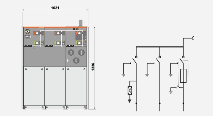
◆ Scheme 2 CCF+
Install lightning arrester into the incoming line and reserve expansion.
◆ Scheme 3 W+M+FFF
HV side calculation
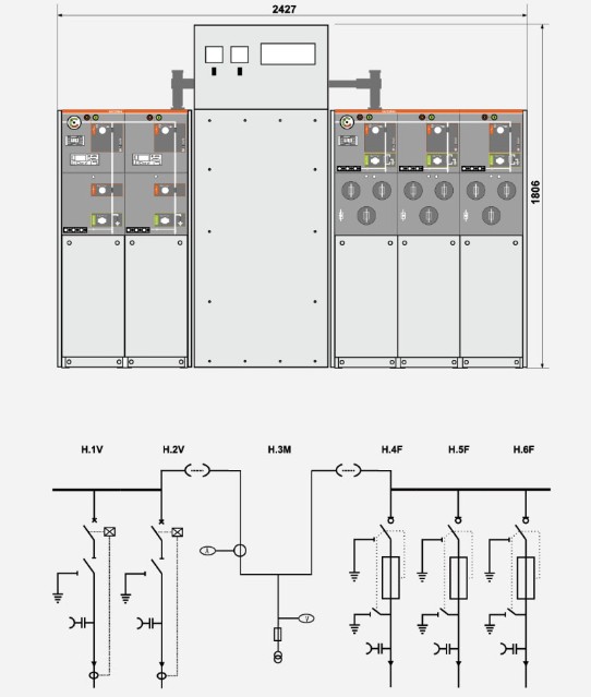
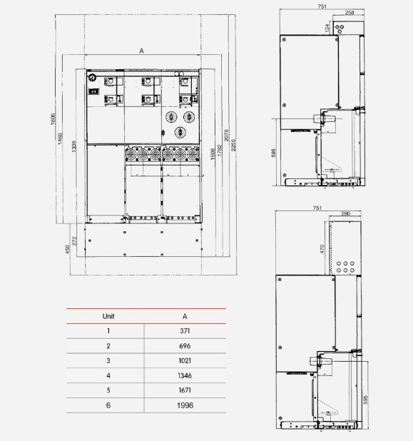
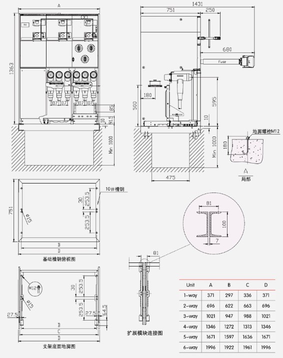
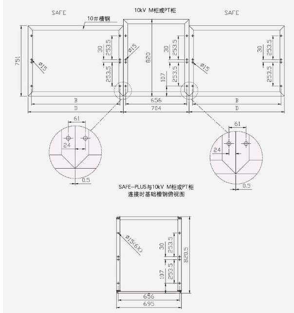
● Structure and dimensions tables of KXRM6-12 Combined Type GIS Cabinet
Send Inquiry
Contact Info
-
Address
No.228 Weishiqi Road, Yueqing Economic Development Zone, Wenzhou City, Zhejiang Province, China
-
Tel
-
For inquiries about cable branch box, high voltage switchgear, low voltage switchgear or price list, please leave your email to us and we will be in touch within 24 hours.
Related Products




News Recommendations