


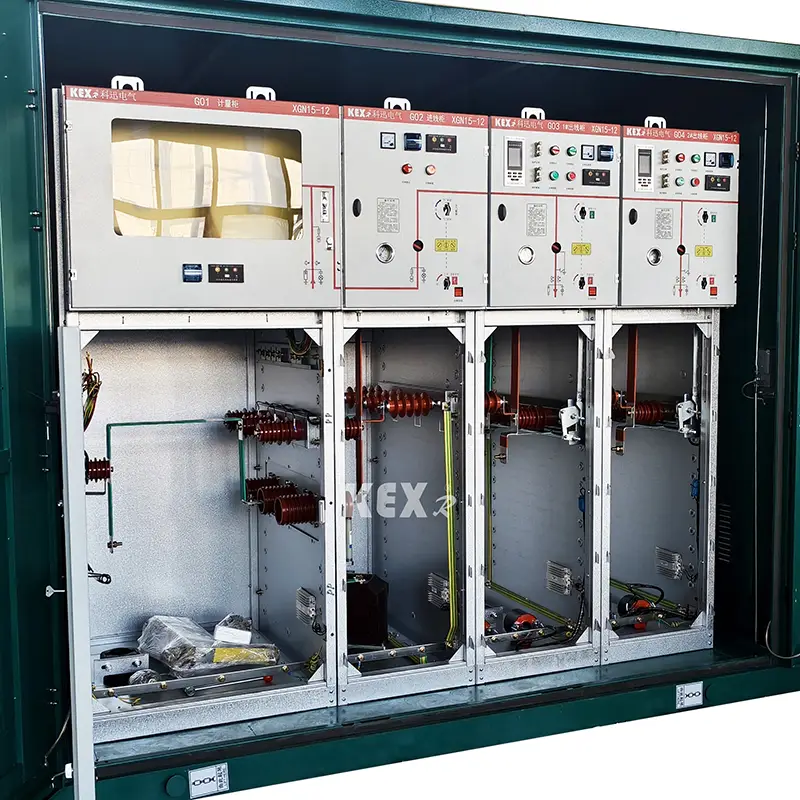
SF6 Ring Main Unit Cabinet
XGN15-12 type SF6 Ring Main Unit Cabinet specialize produced by Chinese factory Kexun Electric Co.,Ltd is suitable for AC 50HZ and 12kV power systems, widely used in industrial and civil cable ring networks and power supply terminal projects, especially in urban residential areas, small secondary substations, industrial and mining enterprises, shopping malls, airports, subways, wind power generation, hospitals, stadiums, railways, tunnels and other places.
Model: XGN15-12
Brand:KEXR
Model: XGN15-12
Brand:KEXR
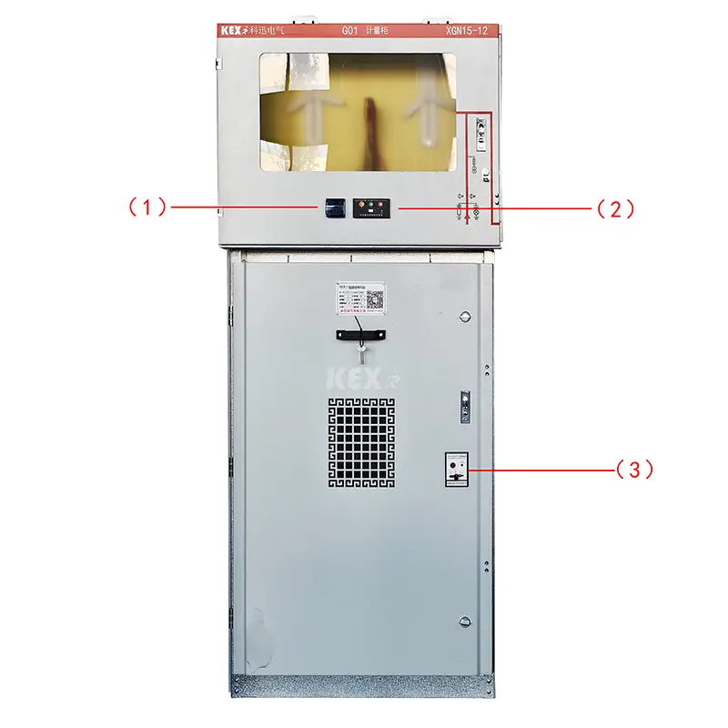
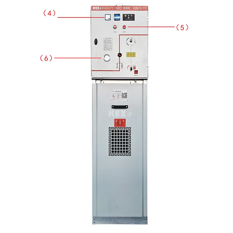
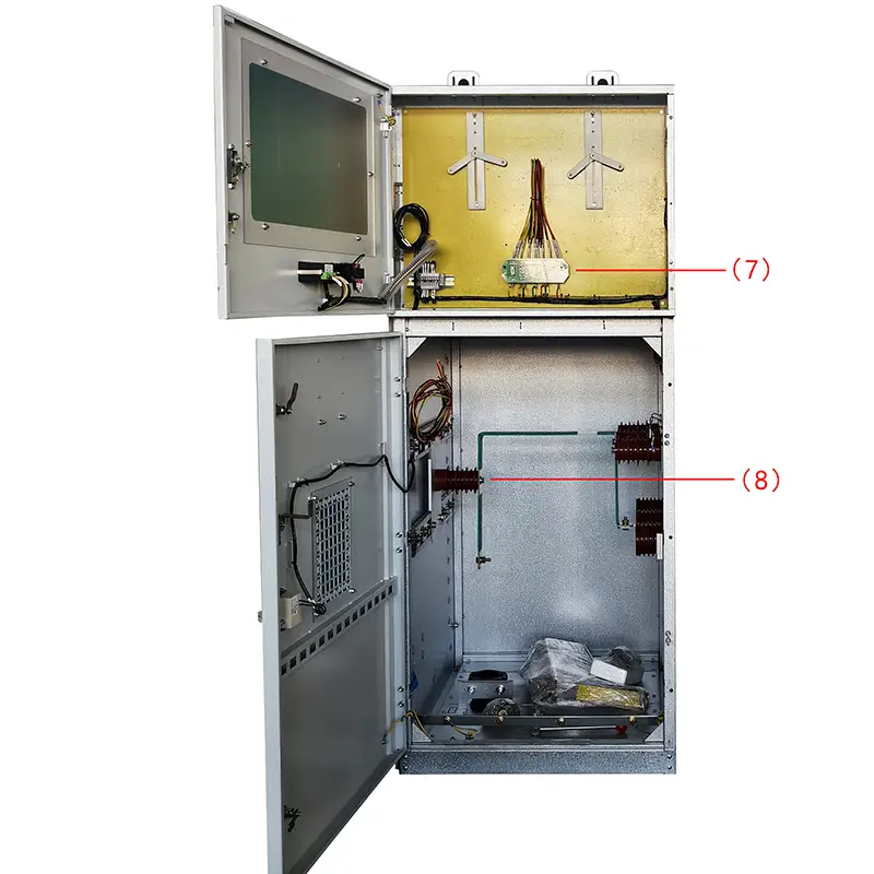
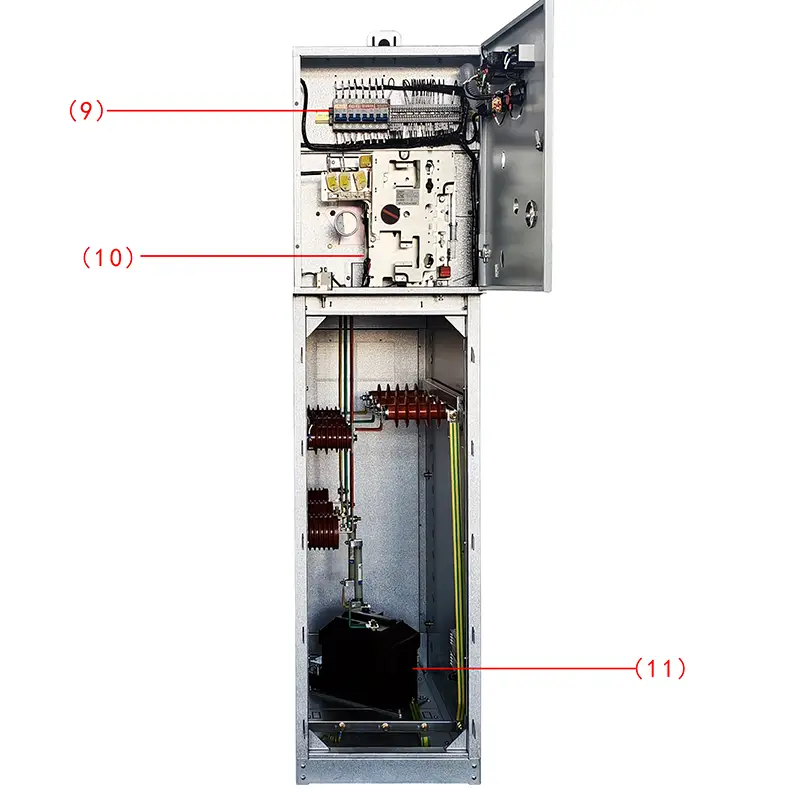
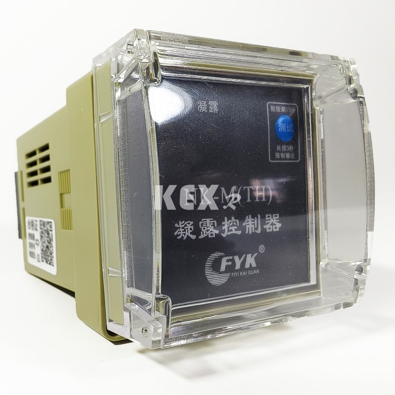
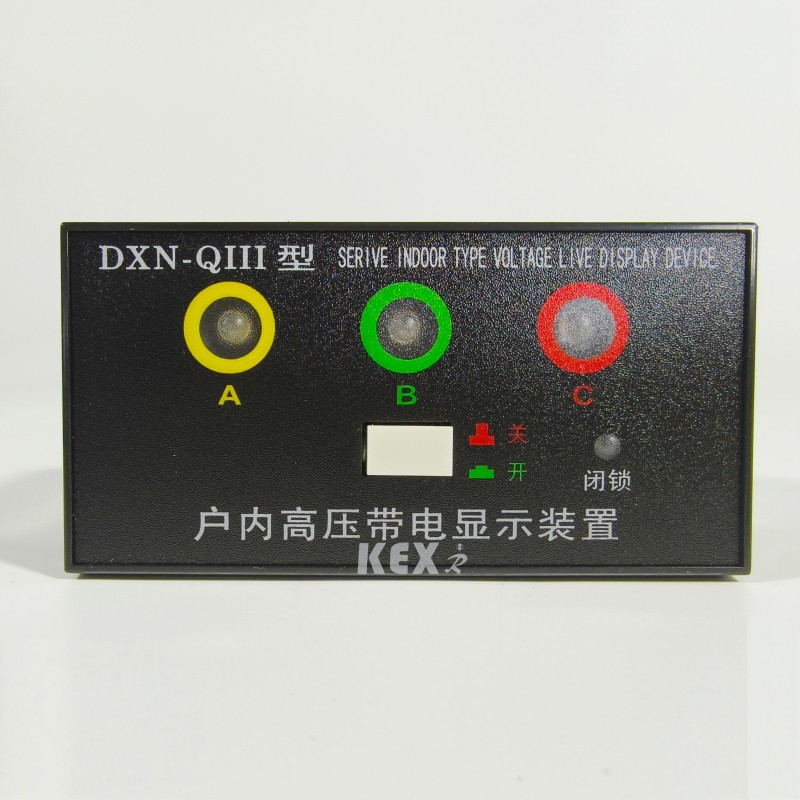
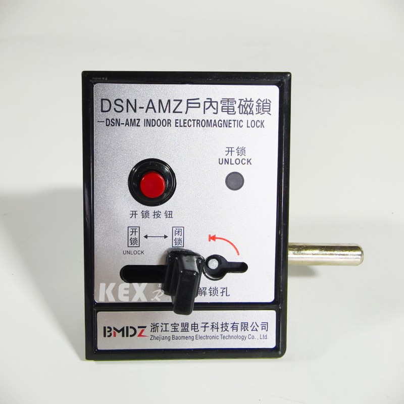
●Components
1. .Condensation controller
2.Charged display
3.Indoor electromagnetic lock
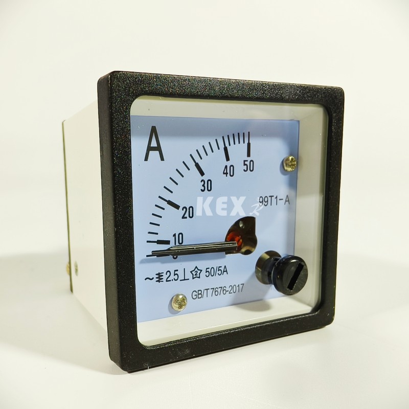
4. Ammeter
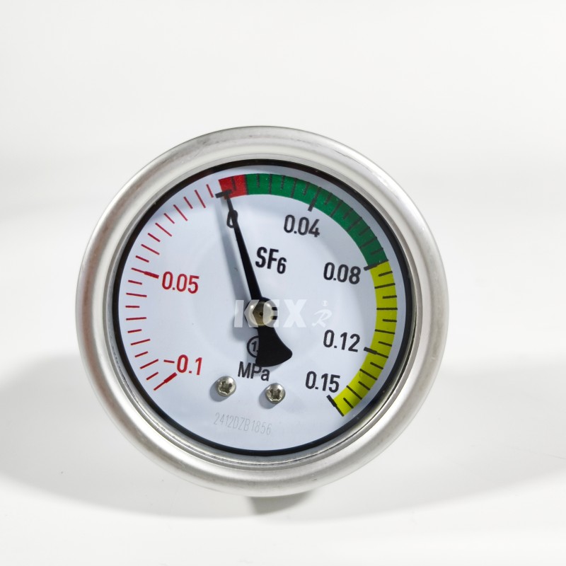
6.Barometer
7. 3 Phase 3 wire electrical connector
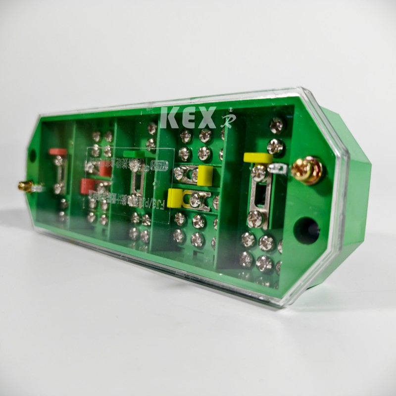
8.Transmitter
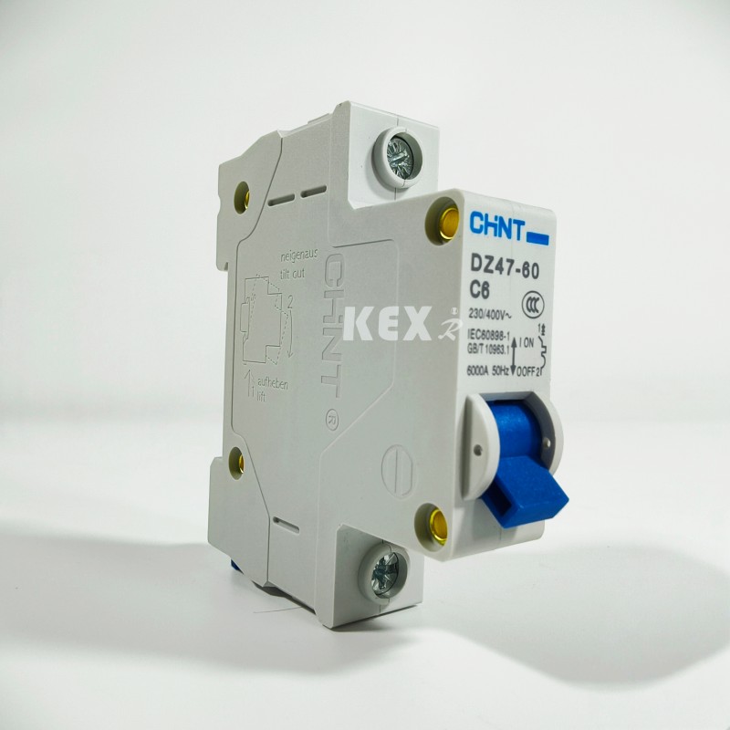
9. Mcb
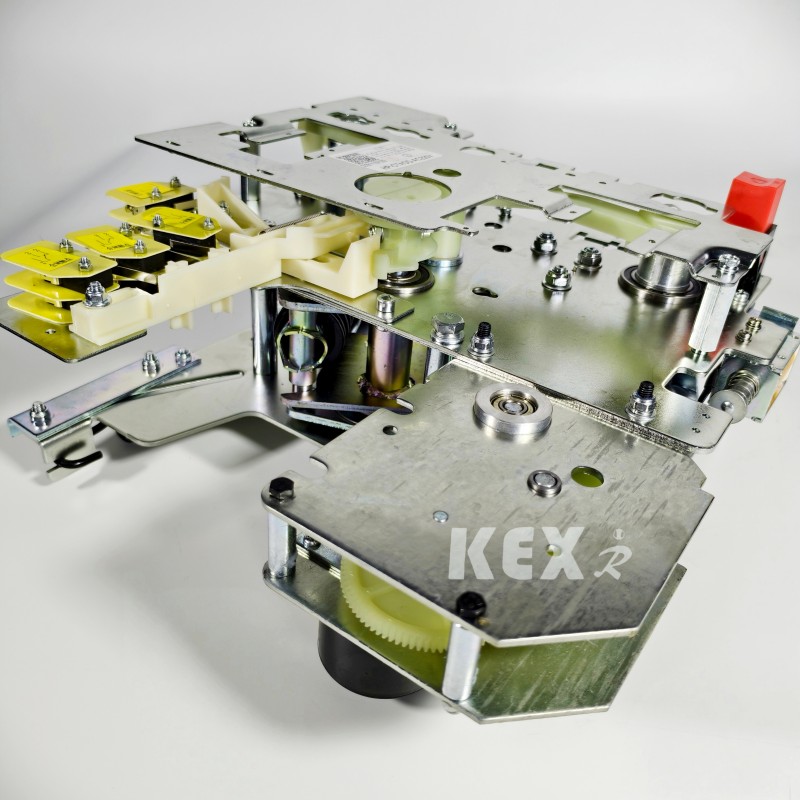
10. Operating mechanism
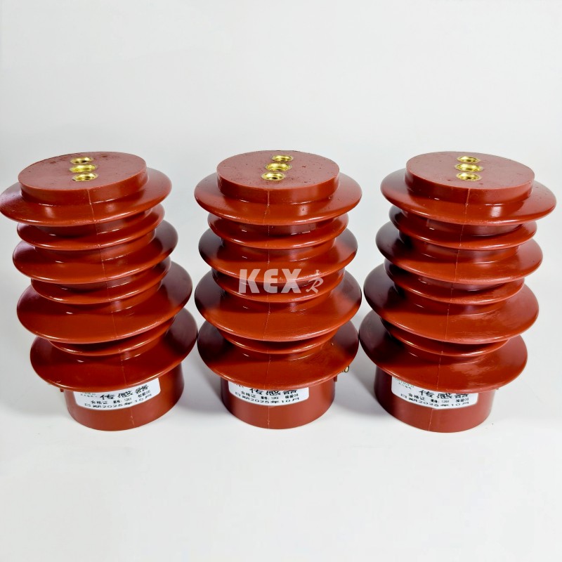
11.VT
● Using conditions
XGN15-12 type modular SF6 Ring Main Unit Cabinet is a new generation of compact and expandable metal enclosed switchgear with sulfur hexafluoride switch as the main switch and air insulation for the whole cabinet. It has the characteristics of simple structure, flexible operation, reliable interlock and convenient installation, and can provide satisfactory technical solutions for various applications and different user requirements. It adopts sensing technology and the latest protective relay, plus advanced technical performance and light and flexible assembly scheme, which can fully meet the changing needs of the market.
The main switches of XGN15-12 SF6 Ring Main Unit Cabinet adopt FLN36 and FLN48 respectively, SF6 load switches and ABB original SFG, and ABB original VD4/S, HD4/S circuit breakers and VS1 circuit breakers can also be equipped according to users' needs.
● Working Environment
◆ Altitude≤1000m
◆Ambient Temperature -25~40℃
◆The average daily relative humidity does not exceed 95%; The average monthly relative humidity does not exceed 90%;
◆ Seismic capacity: 8 degrees;
◆ No violent vibration and impact, and places with fire, chemical corrosion and explosion hazards.
● Stadards
XGN15-12 modular SF6 Ring Main Unit Cabinet meets the standards below
IEC298 ·IEC265 ·IECL29 ·IEC694 ·IEC420 ·IEC56 ·IEC529 ·IEC932 ·GB3804 ·GB3906 ·GB11022
●Technical parameter table of the XGN15-12 type modular SF6 Ring Main Unit Cabinet
|
Item |
|
Unit |
Data |
|
Rated voltage |
|
KV |
12 |
|
Rated lightning impulse withstand voltage |
Alternate and ground |
KV |
75 |
|
break |
KV |
85 |
|
|
1min Power withstand voltage |
Alternate and ground |
KV |
42 |
|
break |
KV |
48 |
|
|
Rated frequency |
Main bus |
Hz |
50 |
|
Branch bus |
Hz |
60 |
|
|
Rated current |
Main circuit |
A |
630 |
|
Grounding circuit |
A |
630 |
|
|
Rated short-term withstand current |
KA |
20/3s |
|
|
Rated peak withstand current |
KA |
20/2s |
|
|
Transfer current |
A |
1700 |
|
|
IP degree |
|
IP2X |
|
|
Load switch mechanical life |
Time |
2000 |
|
|
Ground switch mechanical life |
Time |
2000 |
|
|
Load switch cabinet |
Width |
mm |
375,500,750 |
|
Depth |
mm |
917,940,980 |
|
|
Height |
mm |
1635,1885 |
|
|
Low voltage room |
Height |
mm |
350,450 |
|
Breaker cabinet |
Width |
mm |
750 |
|
Depth |
mm |
917,940,980 |
|
|
Height |
mm |
1885 |
|
● The structure of XGN15-12 type modular SF6 Ring Main Unit Cabinet
◆Busbar room: load switch
A three-station load switch is installed in the switch room. The shell of the load switch is made of epoxy resin and filled with sulfur hexafluoride (SF6 ) The gas is an insulating medium, and S6F can be installed in the switch room according to customer's requirements. Gas density meter or gas density meter with alarm contact.
◆Cable room: operating mechanism, interlocking mechanism and low voltage control room.
The load switch cabinet has ample cable room, which is mainly used for cable connection, so that single-core or three-core cables can be connected by simple unshielded cable heads, and at the same time, lightning arrester, current transformer, lower grounding switch and other elements can be installed in ample space. According to the standard design, the cupboard door has observation window and safety interlock device, and the bottom plate of cable room is equipped with sealing cover and cable clamp with support frame of appropriate size. The bottom plate and front door frame of the cable room can be removed to facilitate cable installation.
◆ Kneading mechanism, interlocking mechanism and low-pressure control room
The low-voltage chamber with interlock plays the role of control panel at the same time. The low-voltage chamber is equipped with spring operating mechanism with position indicator, mechanical interlock and device, and can also be equipped with auxiliary contacts, tripping coil, emergency tripping mechanism, capacitive live display, key lock and electric operating device. At the same time, the space in the low-voltage chamber can also be equipped with control circuit, measuring instrument and protective relay. The 750mm wide cabinet has two identical low-voltage chambers, which can be equipped with more accessories. The whole XGN15 switch cabinet can be divided into two parts, the upper part of the cabinet includes bus room, load switch, operating mechanism and low-voltage room, which is separated from the lower cable room. Therefore, the equipment installed in the upper unit can be safely and conveniently overhauled and reformed, and the whole upper unit can be replaced.
◆ Busbar room
The busbar room is arranged in the upper part of the cabinet. In the bus room, the main buses are connected together and run through the whole row of switchgear.
● The basic components of XGN15-12 type modular SF6 Ring Main Unit Cabinet
▶FLN36 type SF6 load switch is developed and produced for the company by introducing foreign technology and according to the requirements of domestic power system,it has three working states:Closing, opening and grounding
▶The dynamic and static contacts of the load switch are placed in the die-casting epoxy resin shell with reinforced structure, SF6 gas is used as arc extinguishing medium, and the air pressure is 14bar. Each load switch is sealed and maintenance-free, and the barometer can be selected separately. The installation method of the load switch is to place a steel partition between the cable room and the bus room, and install it horizontally to meet the most stringent safety requirements for operation and maintenance. If arcing occurs inside, there is a structural weak point at the back of the load switch shell, which will be washed away, and then the arc discharge valve on the cabinet will be washed away to guide the over pressure airflow outside the cabinet.
▶The SF6 load switch has two operating mechanisms: Single spring operating mechanism (K-type) and double spring operating mechanism (A-type), the electric mechanism can be added to the above two types of operating mechanisms to realize remote electric control.
●Schemes for choose
□Example Scheme 1
|
Primary Program Number |
D01 |
|
Main busbar TMY-3140×8) |
|
|
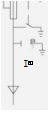
XGN15-12 Primary system diagram |
|
|
To configure |
Incoming cabinet |
|
Load switch FLN36-12 |
1 |
|
Load switch FLRN36-12D |
|
|
Live Display DXN-T |
1 |
|
Current Transformer LZBJ9-10 |
|
|
A Fuse XRNT |
|
|
Voltage Transformer JDZ-10/0.1KV |
|
|
Surge arrester HY5WS-17/50 |
3 |
|
Fuse XRNP-10/□A |
|
|
Measuring instrument |
|
|
Protection mode |
|
|
Auxiliary function |
|
|
Operation mode |
Manual operation |
|
Cabinet W×D×H(mm) |
375×1000×1635 |


◆Standard Configuration and Characteristics
▶630A Bus
▶Load switch:FLN36-12D/T630-20
▶Three-station load switch (closing,isolating,grounding)or two-station switch (closing, isolating)
▶Visual windows are installed at the operating end of the switch.
▶The main switch and grounding switch are operated by two separate operation holes and each other is self-locking.
▶Position indication of load switch and grounding switch
▶Switch body with capacitive voltage indicator
▶SF6 gas pressure gauge with density relay
▶Grounding switch interlocking with front panel of cable room
◆ Optional configuration and features
▶Reserved Bus Extension
▶Load switching operation motor:AC220V/110V DC220V/110V/48V
▶Short Circuit and Grounding Fault Indicator
▶Lightning Protection Device (Distribution Type,Power Plant Type,Release Type)
▶Measuring CT and Meter
▶Voltage Transformer PT for Operating Power Supply
▶AC110V/220V Live Grounding Closure of Inlet Line (Grounding Switch and Lower Gate of Closed Grounding Closure when Lower Cable is Live)
▶Auxiliary Contact:Main Switch 4NO+4NC Grounding Switch 2NO+2NC
□Example Scheme 2
|
Primary Program Number |
D08 |
|
Main busbar TMY-3140×8) |
|
|
XGN15-12 Primary system diagram |
|
|
To configure |
Outlet cabinet |
|
Load switch FLN36-12 |
|
|
Load switch FLRN36-12D |
1 |
|
Display DXN-T |
1 |
|
Current Transformer LZBJ9-10 |
|
|
A Fuse XRNT |
3*XRNTI(A |
|
Voltage Transformer JDZ-10/0.1KV |
|
|
Surge arrester HY5WS-17/50 |
|
|
Fuse XRNP-10/□A |
|
|
Measuring instrument |
|
|
Protection mode |
|
|
Auxiliary function |
|
|
Operation mode |
Manual operation |
|
Cabinet W×D×H(mm) |
375×1000×1635 |

◆ Standard Configuration and Characteristics·
▶630A main busbar
▶Load switch:FLN36-12D/T100-50
▶Three-station load switch (closing,isolating and grounding)
▶Three-station load switch,fuse head and fuse end grounding switch
▶For mechanical linkage
▶Fuse trip indication and remote signal transmission
▶A visual window is installed at the switch operating end.
▶The main switch and grounding switch are operated by two separate operation holes and each other is self-locking.
▶Position indication of load switch and grounding switch
▶Switch body with capacitive voltage indicator
▶SF6 gas pressure gauge with density relay
▶Grounding switch interlocking with front panel of cable room
◆ Optional configuration and features
▶Reserved Bus Extension
▶Load switching operation motor:AC220V/110V DC220V/110V/48V
▶Short and Grounded Fault Indicator
▶Measuring CT and Meter
▶Loss Voltage Trip AC220V
▶Overcurrent disconnector:GL25/5
▶Auxiliary contacts:main switch 4NO+4NC grounding switch 2NO+NC
▶Trip coil:AC220V/110V DC220V/110V/48V
▶Fuse Fuse (Fault Signal):1NO
▶Pressure gauge with signal:1NO
□Example Scheme 3
Primary Program Number D07
|
Main busbar TMY-3(40×8) |
|
||
|
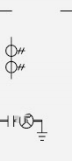
XGN5-12 Primary system diagram |
|
K |
|
|
|
|||
|
To configure |
Metering cabinet |
||
|
Load switch FLN36-12 |
|
||
|
Load switch FLRN36-12D |
|
||
|
Display DXN-T |
1 |
||
|
Current Transformer LZBJ9-10 |
2 |
||
|
Fuse XRNT□A |
|
||
|
Voltage Transformer JDZ-10/0.1KkV |
2 |
||
|
Surge arrester HY5WS-17/50 |
|
||
|
Fuse XRNP-10/□A |
3 |
||
|
Measuring instrument |
|
||
|
式Protection mode |
|
||
|
Auxiliary funclion |
|
||
|
Operation mode |
|
||
|
Cabinet W×D×H(mm) |
750×1000×1635 |
||


◆Standard Configuration and Characteristics
▶Two LZZBJ9 Current Transformers
▶Two JDZ Voltage Transformers
▶Protect PT fuse
▶Interlocking of front panel of cable room
◆Optional configuration and features
▶AVoltmeter with Switch
▶A ammeter with a switch
▶3 CT ,3 PT
▶Capacitive Voltage Indicator Indicating Live Switchgear Cabinet
▶Watt hour meter
▶Negative control
Hot Tags: SF6 Ring Main Unit Cabinet
Send Inquiry
Contact Info
-
Address
No.228 Weishiqi Road, Yueqing Economic Development Zone, Wenzhou City, Zhejiang Province, China
-
Tel
-
E-mail
For inquiries about cable branch box, high voltage switchgear, low voltage switchgear or price list, please leave your email to us and we will be in touch within 24 hours.


