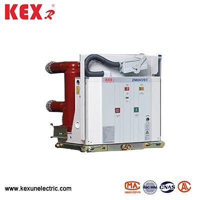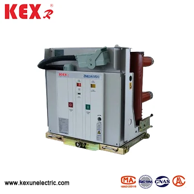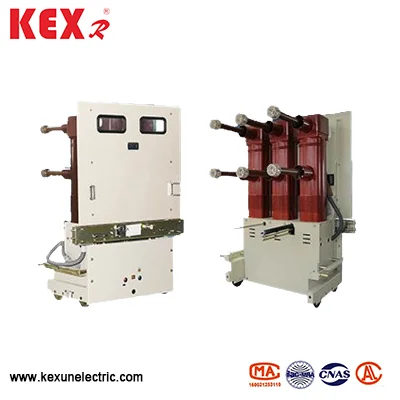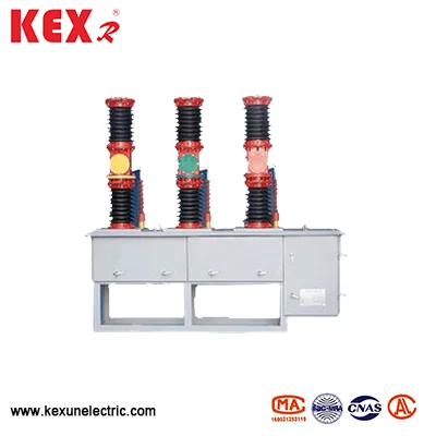

Three Pole Outdoor Vcb
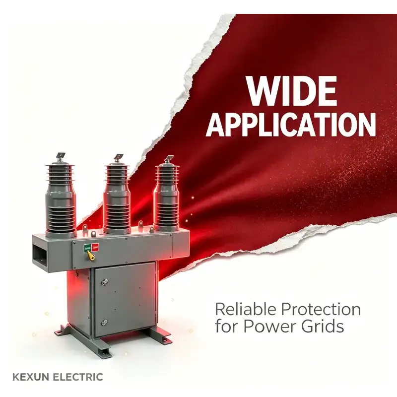
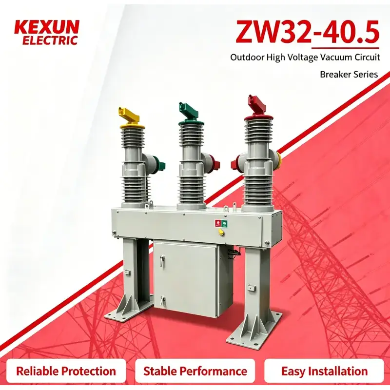
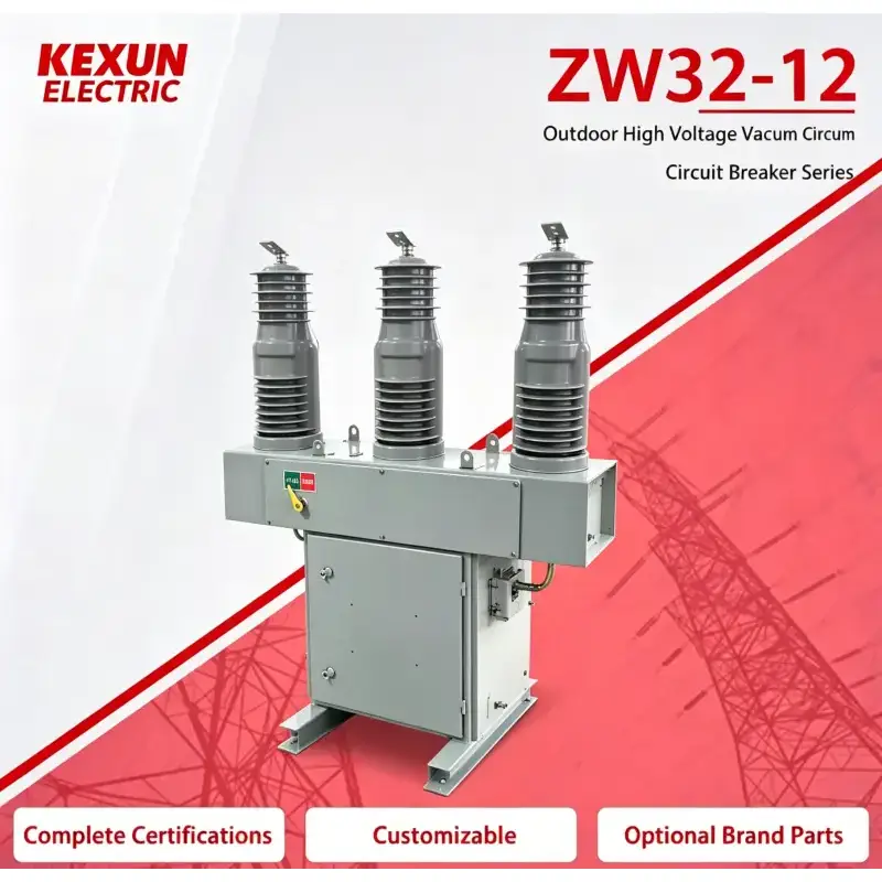
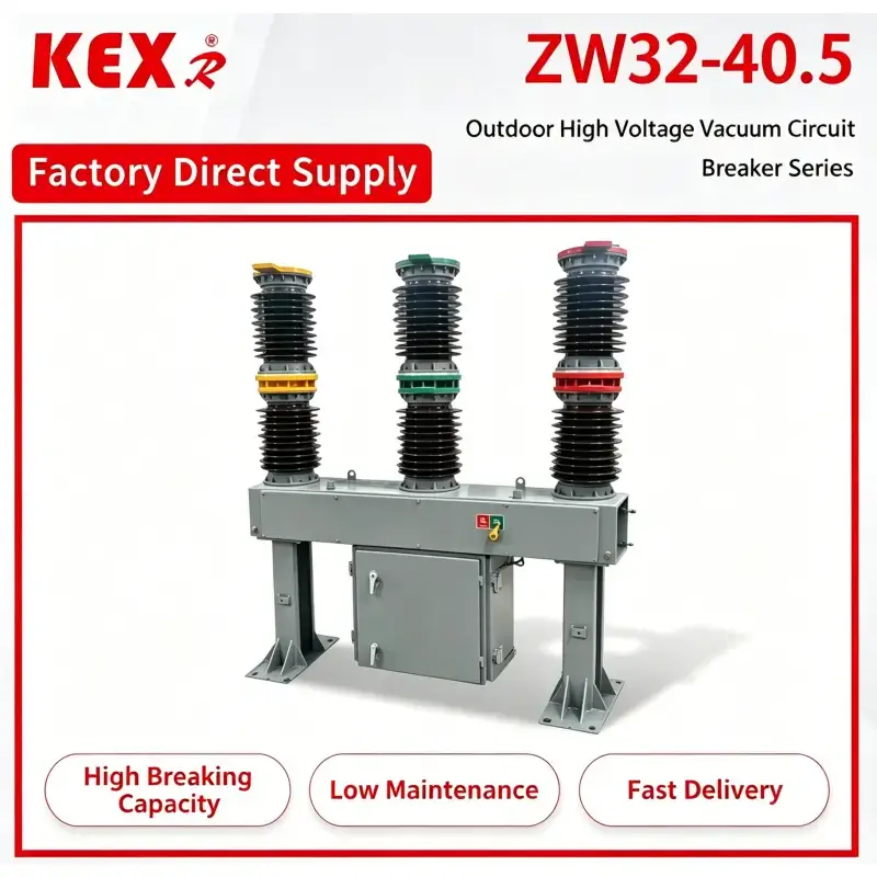
ZW7-40.5 type three pole outdoor vcb adopts a unique design of integrated magnetic pole and a highly reliable operating mechanism. The device is mainly used in medium-voltage overhead power grid, which is used for dividing and combining load current, overload current and short-circuit current.
ZW7-40.5 type Three pole outdoor vcb Product features
Extremely high reliability
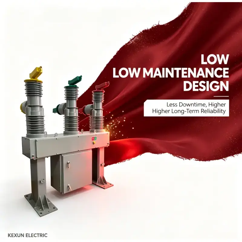
Completely maintenance-free during the whole life.
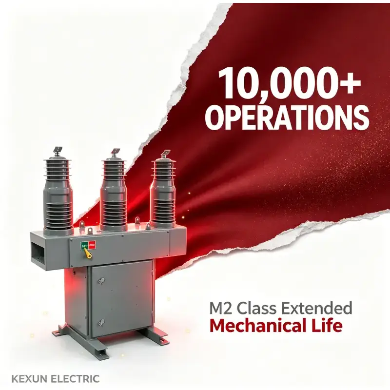
Has high mechanical life and electrical life.
The whole machine is small in size, light in weight and easy to install.
Using conditions of ZW7-40.5 type Three pole outdoor vcb
¨ Ambient temperature:-30℃~60℃;
¨ Altitude:less than 3000m;
¨ Wind speed :≤34m/s;
¨ Vibration or ground motion from outside the switchgear and control equipment can be ignored.;
¨ Pollution Grade:Ⅳ;
¨ Storage temperature:-40℃~85℃。
1.2 Technical parameter of ZW7-40.5 type Three pole outdoor vcb
Main technical parameter of circuit breaker
|
Number |
Item |
Unit |
Data |
|
1 |
Rated voltage |
kV |
40.5 |
|
2 |
Rated current |
A |
1250~2500 |
|
3 |
Rated frequency |
Hz |
50或60 |
|
4 |
Working frequency withstand voltage1min(wet)(dry) P to P、to earth/break |
kV |
80 /90/95 |
|
5 |
Lightning impulse withstand voltage(peak) P to P、to earth/break |
kV |
185 |
|
6 |
Rated short circuit break current |
kA |
25/31.5 |
|
7 |
Rated short circuit close current(peak) |
kA |
63/80 |
|
8 |
Rated peak withstand current |
kA |
63/80 |
|
9 |
4S short-term withstand current |
kA |
25/31.5 |
|
10 |
Rated operation circle |
|
分-0.1s-CO-3s-CO-6sCO-60s |
|
11 |
Rated short circuit current breaking times |
time |
30 |
|
12 |
Mechanical life |
time |
10000 |
|
13 |
Control voltage |
V |
AC/DC220 |
|
14 |
Secondary circuit 1min working frequency voltage |
KV |
2 |
Main mechnical parameter of circuit breaker
|
Number |
Item |
Unit |
Data |
|
1 |
Contact distance |
mm |
20±2 |
|
2 |
Contact overtravel |
mm |
4±0.5 |
|
3 |
Opening speed |
m/s |
1.4-1.8 |
|
4 |
Closing speed |
m/s |
0.4-0.8 |
|
5 |
Contact closing bounce time |
ms |
≤5 |
|
6 |
Phase to phase distance |
mm |
700±2 |
|
7 |
Different periods of three-phase opening and closing |
ms |
≤2 |
|
8 |
Resistance of each phase conductive loop |
μΩ |
<80 |
|
9 |
Closing time |
ms |
≤100 |
|
10 |
Opening time |
ms |
≤50 |
|
11 |
Weight |
Kg |
600 |
Structure and working principle of circuit breaker
ZW7-40.5 Three pole outdoor vcb is mainly composed of integrated magnetic pole, current transformer, operating mechanism and box. This type of circuit breaker is miniaturized and its shell is made of high-quality stainless steel box. Current transformer can be selected according to user's needs.
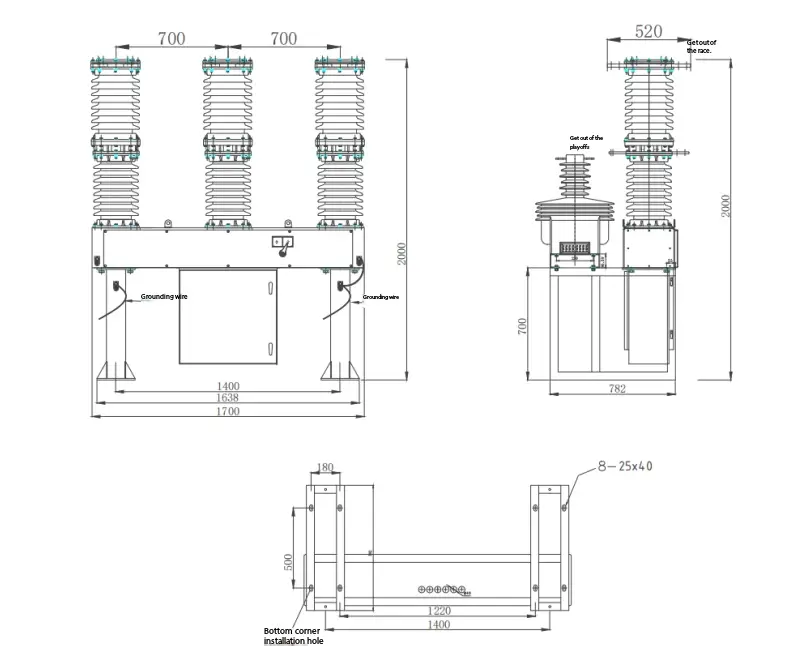
ZW7-40.5/circuit breaker outline drawing
ZW7-40.5 Three pole outdoor vcb and its intelligent control combination. The on-off operation of the switch can be realized locally, and it can also be operated remotely through the communication interface. Other information of the circuit breaker can also be transmitted to the control center, and the communication channel can be cable, optical fiber, GPRS/CDMA, GSM, etc.
Working principle of circuit breaker
3.1Arc extinguishing principle:
ZW7-40.5 Three pole outdoor vcb adopts vacuum interrupter, and vacuum is used as arc extinguishing and insulating medium, which has extremely high vacuum degree. When the moving and static contacts are switched off with electricity under the action of the operating mechanism, a vacuum arc will be generated between the contacts. At the same time, due to the special structure of the contacts, an appropriate longitudinal magnetic field will also be generated in the gap between the contacts, which will promote the vacuum arc to remain diffuse, and make the arc evenly distributed on the contact surface to burn, so as to maintain a low arc voltage. When the current naturally crosses zero, the residual ions, electrons and metal vapor can be combined or condensed on the contact surface and the shield within microsecond order of time. Because the longitudinal magnetic field is used to control the vacuum arc, the vacuum circuit breaker has a strong and stable ability to break the current.
3.2 Electric energy storage:The motor acts the output torque on the pinion of the mechanism and transmits it to the big sprocket on the spindle, thus driving the crank arm to rotate and making the closing spring store energy. When the screw on the crank arm presses the travel switch, the power supply of the motor is cut off, and the spring energy storage is completed.
3.3 Manualenergy storage:The output shaft of that rotate mechanism transmits the rotate torque to the big gear which is fully meshed with the small gear through the pinion on the output shaft, thereby driving the crank arm to rotate, so that the closing spr can store energy.
3.4O peration of closing electromagnet: after the mechanism receives the closing signal, the moving iron core of the closing electromagnet moves upward, pushing the closing trip lever to move upward, so that the closing half shaft rotates counterclockwise. Release the constraint on the closing latch. At the same time, the closing latch rotates counterclockwise under the pressure of the roller, releasing the energy storage maintenance. The cam on the main shaft generates impact force due to the contraction force of the closing spring, and hits the rocker arm on the manual energy storage shaft (that is, the output shaft), which is transmitted to the switch through the connecting rod, thus completing the closing operation.
3.5 Manual operation: When the shift fork installed on the closing half shaft rotates counterclockwise, it drives the closing half shaft to rotate counterclockwise. So as to produce the same effect as the operation of closing electromagnet.
3.6 Reclosing operation: after the mechanism releases the energy of the energy storage spring, it completes the closing operation. In the closing state, the mechanism performs the energy storage operation again. After the energy storage operation is completed, the mechanism is in the closed energy storage state, and once the correct signal is received, the mechanism can realize an automatic reclosing operation.。
3.7 Operation of the brake release electromagnet: after the mechanism receives the brake release signal, the moving core of the brake release electromagnet moves upward, pushing the brake release lever to move upward, so that the brake release axle rotates counterclockwise. Release the constraint on the brake release latch. At the same time, the brake release latch rotates counterclockwise under the pressure of the roller, and the rocker arm rotates counterclockwise due to the thrust of some brake springs in the switch, thus completing the brake release operation.
3.8 Manual operation: When the fork mounted on the brake half shaft rotates counterclockwise, it drives the brake half shaft to rotate counterclockwise, thus producing the same effect as the operation of the brake electromagnet.3.8 Manual operation: When the fork mounted on the brake half shaft rotates counterclockwise, it drives the brake half shaft to rotate counterclockwise, thus producing the same effect as the operation of the brake electromagnet.
3.9 Over-current trip operation: when the over-current coil in the over-current trip passes through the specified trip current, the electromagnet acts and the push rod pushes the trip lever. Make the half-shaft rotate counterclockwise, release the constraint on the brake latch, thus producing the same effect as the operation of the brake electromagnet, and complete the overcurrent tripping operation of the circuit breaker.
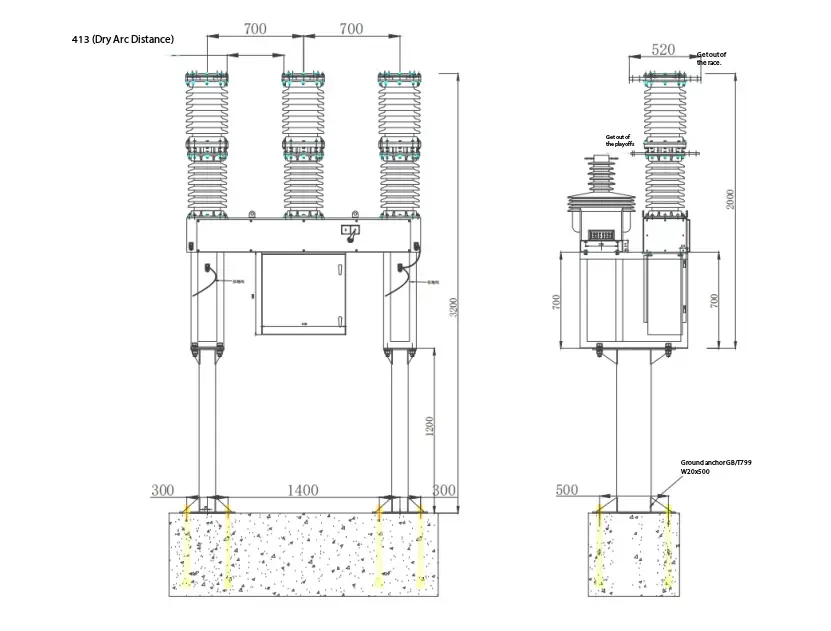
Three pole outdoor vcb Installation diagram
Hot Tags: Three Pole Outdoor Vcb
Send Inquiry
Contact Info
-
Address
No.228 Weishiqi Road, Yueqing Economic Development Zone, Wenzhou City, Zhejiang Province, China
-
Tel
-
E-mail
For inquiries about cable branch box, high voltage switchgear, low voltage switchgear or price list, please leave your email to us and we will be in touch within 24 hours.